PicoMemcard
Design goals and implementation of PicoMemcard, a PSX Memory Card simulator working on real PSX hardware using a Raspberry Pi Pico.
Introduction
I began this project because I was mad that the counterfit Memory Card I bought on Aliexpress was not compatible with FreePSXBoot. I didn’t want to waste more money on a used memory card in questionable conditions, so I thought to myself: “How hard could it be do build your own memory card?”. Turns out it’s not that straight forward.
My very first attempt to do so, was using a Raspberry Pi B+ to read the modified SPI protocol that the PSX uses to communicate with controllers and memory cards. Unfortunately it’s not nearly capable of controlling the GPIO at the speed required for the communication protocol.
Than I stumbled on the Raspberry Pi Pico, the feature that cought my eye was PIO (Programmable I/O): the ability to program a set of state machines to interact with the GPIO on a very low level (therefore fast) leaving the processor able to perform other activities. Thanks to PIO, I was finally able to implement an interface in order to interact with the PSX modified SPI protocol.
Design
When thinking about PicoMemcard I had a two main goals in mind:
- The total cost of building one had to be lower than buying an original memory card.
- It had to be easy to use. I wanted a simple procedure to upload a memory card image onto the Pico.
The first goal ment that I wanted to avoid as much as possible additional external components (e.g. voltage regulators, additional storage modules and so on), which ment that I was stuck with 256KB of RAM and 2MB of NOR flash storage. These specifications are not that impressive, but should be plenty enough to simulate a 128KB memory card right? Turns out there are many caveats when using the Pico on-board flash as data storage.
To meet the second goal, I wanted the Pico to appear as a Mass Storage Class (MSC) device when connected via USB to a computer, presenting a FAT filesystem where the memory card image can be copied to. This apporach can be easily achieved using the TinyUSB library and is exactly what the Pico itself does when connected while pressing the BOOTSEL button.
Filesystem and Flash
Unfortunately storing a FAT filesystem on Pico’s flash isn’t exactly a wise move. In fact, conventional flash-based storage devices have a dedicated flash controller that provides feature such as wear levelling. Additionally they are normally based on NAND flash memory which provides higher storage capacity and it’s easier to reprogram. On the Pico instead we have no such thing, using a FAT filesystem means that a few flash pages would be rewritten very often (e.g. pages containing the File Allocation Table) while others would barely be touched. This would result in very uneven wear of the flash pages which could reduce the lifespan of the device.
To solve this problem I opted to use littlefs (or LFS): a filesystem designed specifically to work on embedded devices NOR flash memory while also providing wear levelling. One problem down, a lot more to go…
Filesystem and MSC
Understandably, we cannot present to the OS (through USB MSC) a disk using LFS because neither Windows nor Linux are equipped with drivers to manipulate such filesystem. Since we still need to present a FAT filesystem but cannot store it in flash memory, so we must store it in RAM! This is what I called “Virtual Disk”, because is the disk that PicoMemcard presents to the OS but is actually stored in RAM and serves as an intermediate to transfer files from the PC to Pico’s flash memory. Using this approach means that the size of our FAT filesystem is limited by the amount of RAM available.
The last question is: when do we perform the transfer from the virtual FAT disk to the actual LFS filesystem stored on flash? Since MSC exposes a block-like interface (where the OS sends commands to read/write blocks and the Pico executes them), we have not much information on what the meaning of these commands are. Has a file transfer been completed? Or did the user only rename a file? Why has a block been written? Did the OS mount the FAT filesystem and updated some of the metadata? Or was it just a file being deleted?
Without this information we don’t have a clear indication on when to perform the transfer to flash. My first solution, was to wait for a fixed period of inactivity after the last write operation and perform the transfer after this timer has expired. Unfortunately I noticed that this triggered the transfer process multiple times even when waiting up to 3 seconds after the last write operation. Could this be a problem for the lifespan of the flash memory? Unlikely, given that the Pico’s rated for 100K program cycles.
Still, I felt that this solution was not quite clean so I opted for a different approach. One piece of information that we can detect through MSC is when the user attempts to safely eject the disk. Using this information we can trigger the transfer process (between virtual FAT disk and LFS stored in flash) after the device has been safely ejected, in this way we ensure that any prior transfer (between the PC and the virtual FAT disk) has been completed and can perform less flash reprogramming operations.
MSC, FAT & LFS
Putting everything back together we have:
- Raspberry Pi Pico, presenting itself as a Mass Storage Class (MSC) device thanks to TinyUSB.
- The virtual FAT disk, created after the PC recognizes the Pico as an MSC device and mounts it. The Pico formats and initializes the virtual disk (using ChaN FatFS library) with a single file containing the memory card image stored in LFS.
- On safe ejection, the Pico reads the new content of the virtual disk (always using ChaN FatFS libray) and flashes it to the LFS filesystem on flash.
Memory Card Simulation
PicoMemcard has two different modes of operation:
- When plugged via USB into a PC it enters “transfer mode” allowing to upload/download a memory card image.
- When powered on and not mounted as an MSC device within 3 seconds, it enters memory card “simulation mode”. Note that powering the Pico via USB with a phone charger will not trigger the mounting process, therefore simulation mode will still be activated.
Simulation Mode and PSX SPI
Once in simulation mode, PicoMemcard will start by copying to RAM the content of the memory card image stored in LFS. At this point all the state machines necessary to communicate with the modified PSX SPI protocol are launched and the different read/write commands targetting the memory card start being processed.
It’s important to underestand that all the read/write commands are carried out using the RAM copy of the memory card image. Why don’t we read and write directly the copy stored in flash? Unfortunately, modifying the flash memory in order to perform a write operation is a very slow process. The Raspberry Pi Pico is fast enough to keep up with the PSX SPI protocol but performing an expensive operation such as flash reprogramming would screw up all the protocol timings resulting in constant miscommunication.
In the end, we must once again resort to an in-RAM copy and perform a sync operation periodically to write-back the modified memory card image to flash. In this case I decided to perform the sync after 1 seconds of inactivity where the PSX is not issuing any “complete” read/write command.
Why do I say “complete” read/write commands? Because the PSX often issues read commands and then interrupts the protocol after the third exchange has occurred (after the memory card sends the ID1 byte, as seen in these specifications).
I’ve noticed that this happens both in the BIOS memory card manager utility as well as in some games. My guess is that after the PSX has read the data that it’s interested in, it begins continuosly issuing read commands and examining the FLAG byte to detect whether the memory card has been changed (physically removed and reinserted). When the memory card has been changed, it starts issuing other “complete” read commands to get the new data. On the other hand, if the memory card has not been swapped, the PSX already knows its content so it interrupts the exchange. To my underestanding, these “incomplete” exchanges are the way the PSX polls for new memory cards.
Due to this behavior, it is still safe to perform the sync operation during polling as it does not result in “complete” read/write command being missed. The downside is that the PSX interprets our missing response to polling as if the memory card was briefly removed. In my experience, even though we send the correct FLAG byte (stating that the memory card has not been swapped) the PSX will issue additional read commmands to verify it.
I’ve tested this in both the BIOS memory card utility and in “Crash Bandicoot 3: Warped”, and it dosn’t seem to cause any problem but it’s a bit annoying.
A better solution would be to use the second core of the Pico to perform the sync while leaving the main core to communicate with the PSX. However this introduces additional problems with the Pico’s flash memory. In fact, when the flash is being programmed it cannot be accessed by cores to execute instructions. This means that we would have to store all the code to execute in RAM which is already mostly filled up by the memory card image. I haven’t tried this approach yet, but I doubt that there is enough RAM for everything.
Future Features
The main feature that I want to implement in the future is adding a microSD SPI breakout board in order to store all the data on a microSD. This would greatly simplify the design on so many points:
- There would be no need to use LFS anymore as the data can be stored on the microSD instead that on the Pico flash.
- There would be no need for a virtual FAT disk since we could provide the PC with direct access to the microSD via MSC.
- Syncing the in-RAM memory card image could be done by the Pico second core without ever interrupting communication with the PSX, avoiding all the associated issues.
The only downside is that the user must buy and assemble an additional component. Fortunately microSD SPI breakout boards are not that expensive, going for about 1-2$ on Aliexpress.
Resources
As a last point, if you are interested in the project and want to learn more, here are some great resources that I found really useful:
- psx-spx and Martin “NO$PSX” Korth - Playstation Specifications and documented Memory Card protocol and filesystem.
- Andrew J. McCubbin - Additional information about Memory Card and Controller comunication with PSX.
Since the communication signal diagram showed on psx-spx are basically ASCII art, I want to make available the data that I captured using Scoppy. These files can be opened using PulseView in order to measure the exact communication timings.
The name of each file is composed as following peripheralX_Y where:
peripheralindicates which peripheral was captured (controller, memory card, or PicoMemcard).Xindicates the slot where the peripheral was plugged in.Yindicates the slot where the Scoppy was sampling.
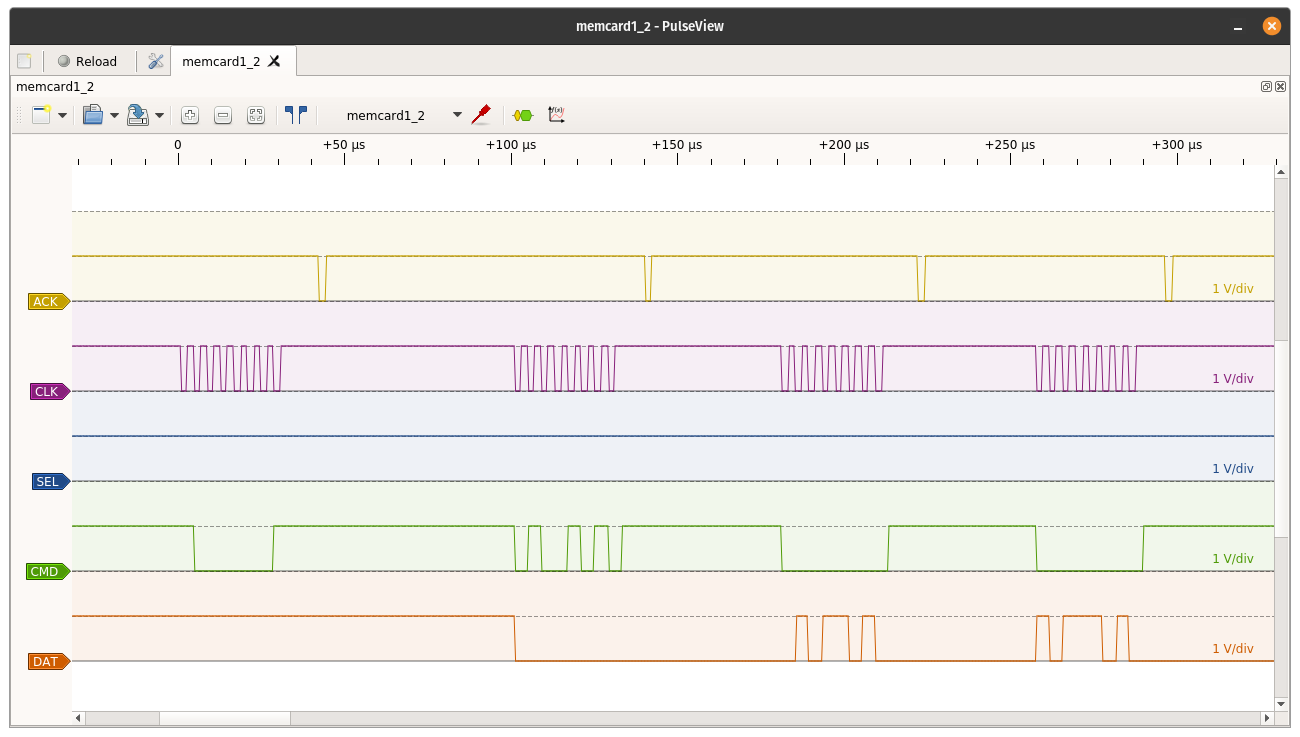
For example memcard1_2 (in the picture above) indicates that Scoppy was capturing the data of a memory card plugged into slot 1 by sampling the lines on slot 2. This is important because as we can see from the logical analyzer the SEL line does not appear to be low during communication. Initially it might seem strange but is in fact correct, as the device communicating is located in slot 1 which has a separate SEL line pulled low, while we are capturing from slot 2 that has the SEL line high.
Captured data: